Logic Gates
Logic Gates - allow our transistors to do more complex tasks, like decide where to send electrical signals depending on logical conditions. They tell a compute hot to perform binary calculations
- specify rules for how to produce an electrical output based on one or more electrical inputs
- used to represent 2 binary states: On or Off; takes in one or more of these binary states and determines whether to pass along an on or off signal
- can be linked together to create complex electrical systems (circuits) that perform complicated binary calculations
Here’s a schematic drawing for a small circuit built with gates described above:
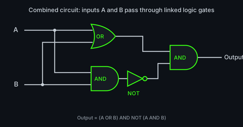
Here is the truth table for this circuit:
| A | B | A OR B | A AND B | NOT (A AND B) | Output |
|---|---|---|---|---|---|
| 0 | 0 | 0 | 0 | 1 | 0 |
| 0 | 1 | 1 | 0 | 1 | 1 |
| 1 | 0 | 1 | 0 | 1 | 1 |
| 1 | 1 | 1 | 1 | 0 | 0 |
6 Common Logic Gates:
-
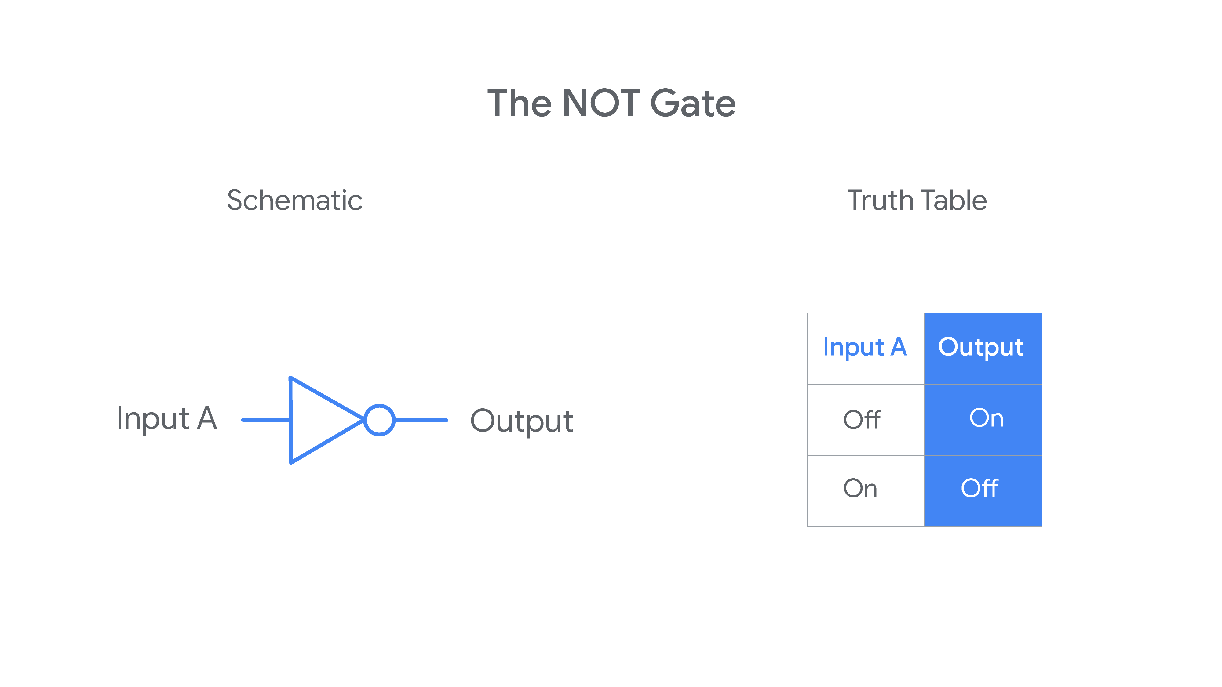
NOT Gate
- simplest; only has one input signal
- takes input signal and outputs a signal with opposite binary state
- ex. input signal is “on”, then NOT Gate outputs “off” signal
-
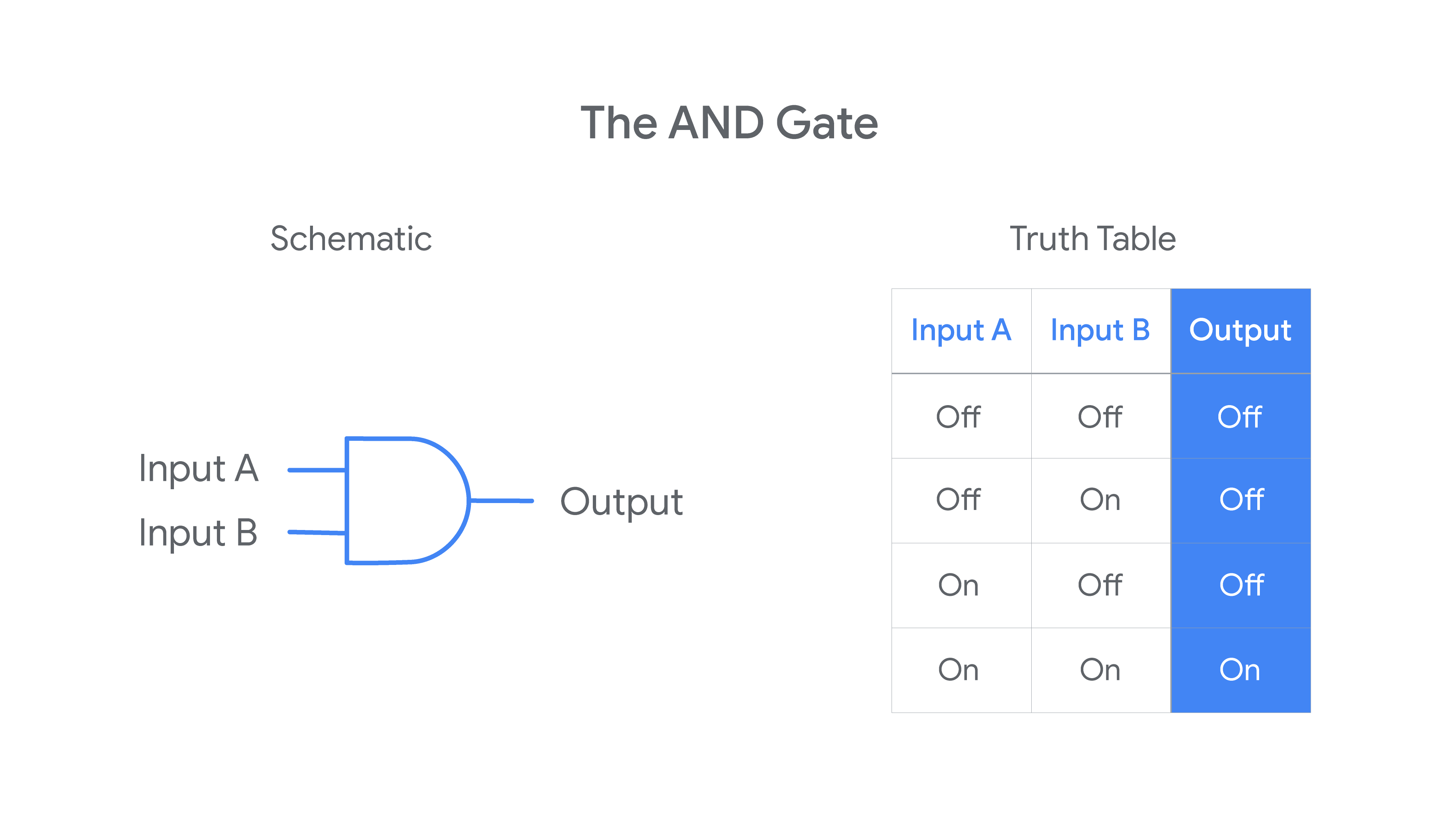
AND Gate
- involves 2 input signals, meaning 4 possible combinations on input values
- AND rule outputs and “on” signal when BOTH inputs are “on”, otherwise output will be “off”
-
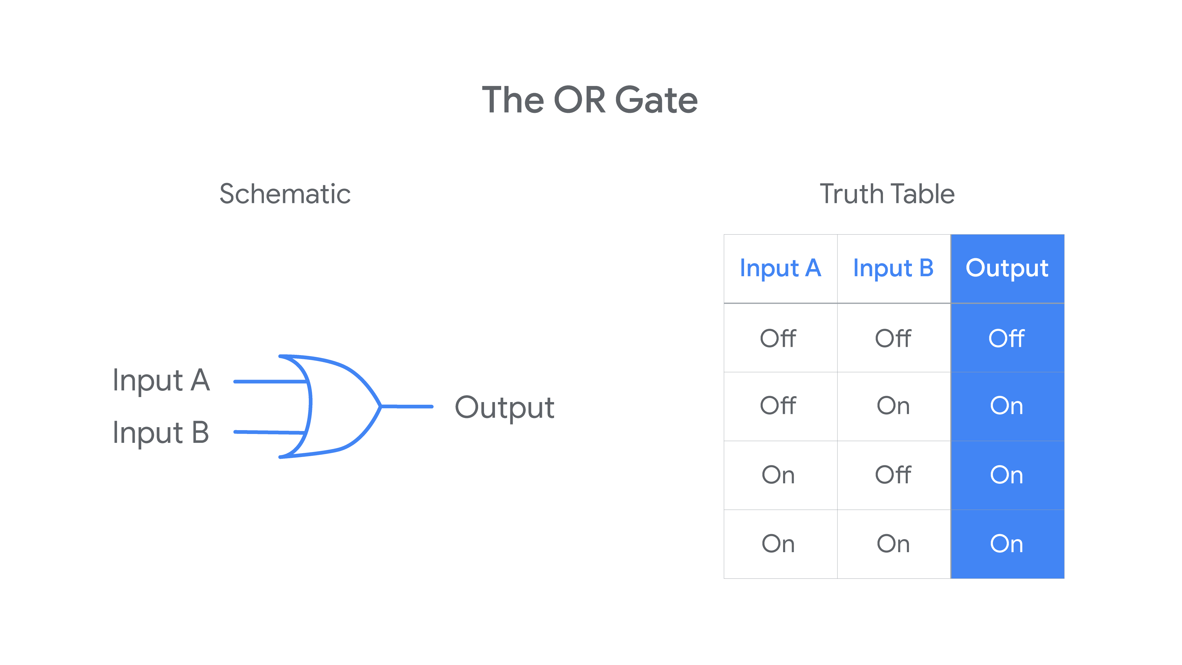
OR Gate
- involves 2 input signals as well
- OR rule outputs and “off” signal when BOTH inputs are “off”, otherwise output will be “on”
-
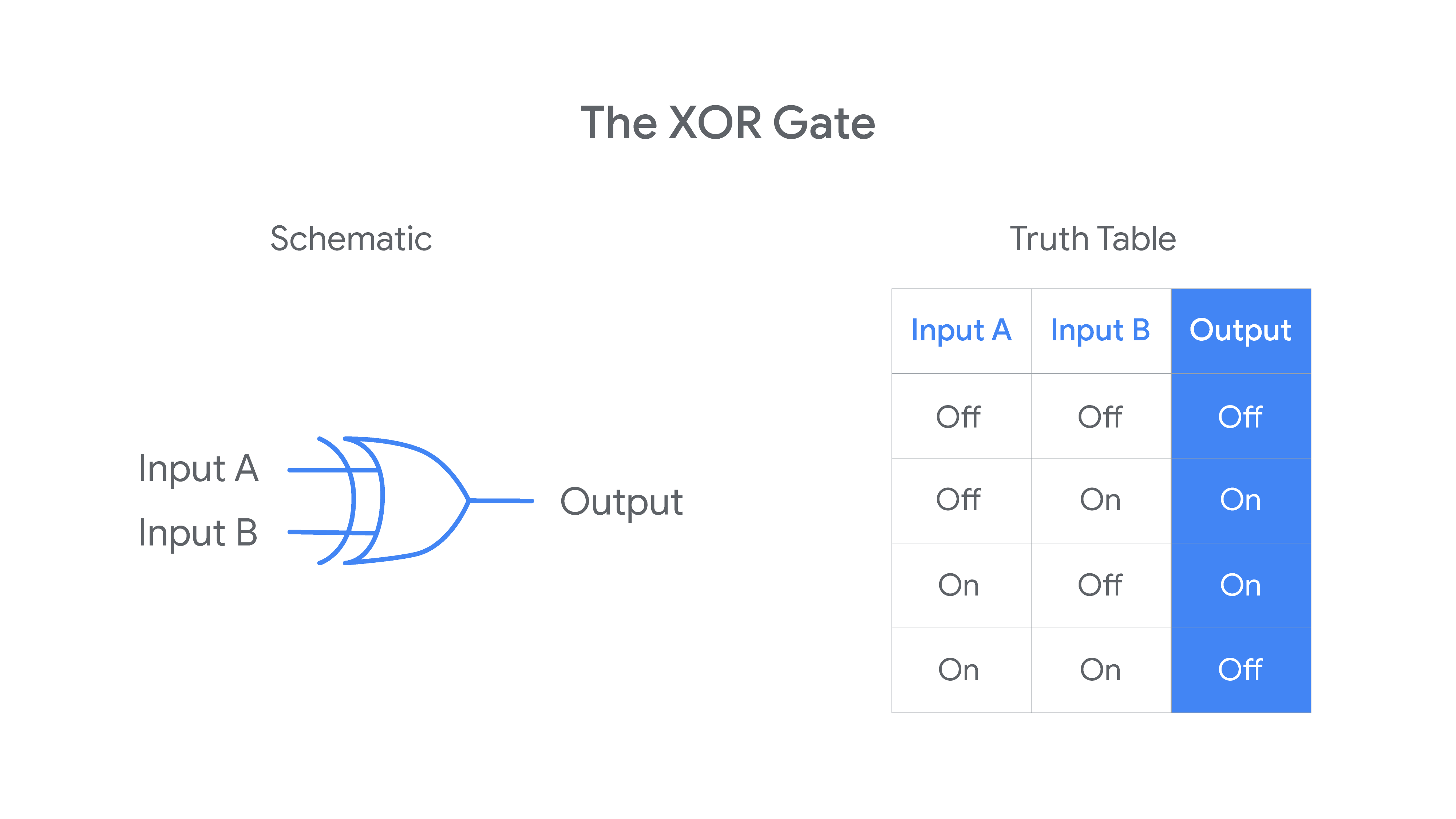
XOR Gate (aka exclusive OR Gate)
- involves 2 input signals
- XOR rule outputs an “on” signal when only one (but not both) of inputs are “on”, otherwise output signal will be “off”
-
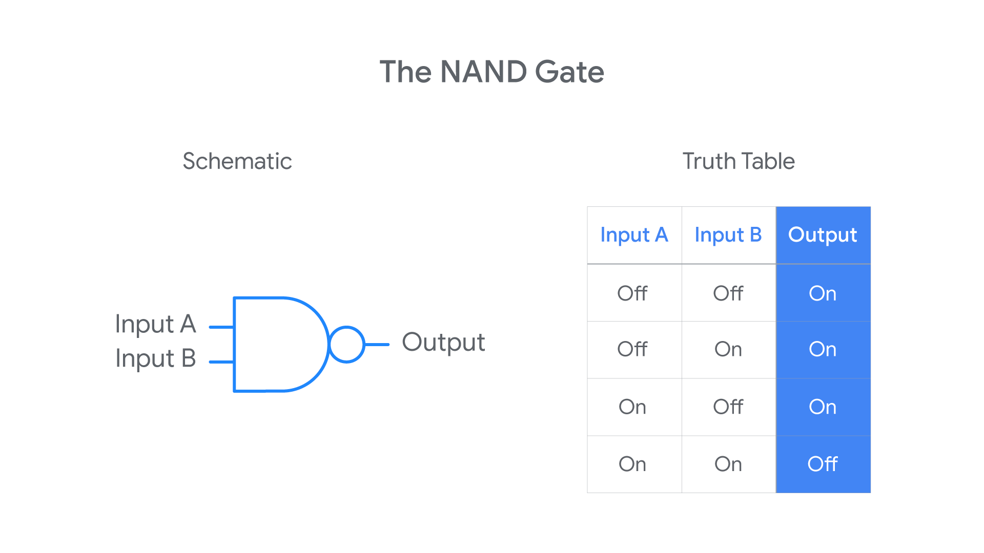
NAND Gate (aka not-AND Gate)
- involves 2 input signals
- outputs an “off” signal only when both inputs are “on”, otherwise output will be “on”
- outputs are opposite of AND outputs
- combination of AND & NOT rules
-
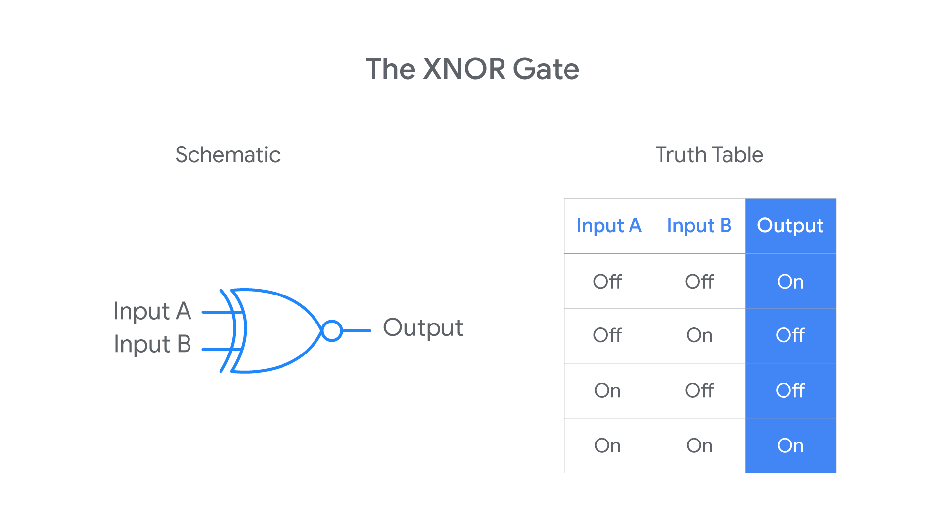
XNOR Gate (aka not-XOR Gate)
- involves 2 input signals
- outputs “on” only when both inputs are the same (both “on” or both “off”), otherwise output will be “off”
- takes the XOR output and runs it through the NOT rule
- combination of XOR rule and NOT rule
Key takeaways
Logic gates are the physical components that allow computers to make binary calculations.
- Logic gates represent different rules for taking one or more binary inputs and outputting a specific binary value (“on” or “off”).
- Logic gates can be linked so that the output of one gate serves as the input for other gates.
- Circuits are complex electrical systems built by linking logic gates together. Computers are this kind of complex electrical system.